-
-
- 2. Connect your Interface
- 2.1.1
 Prepare your BlackBox
 -
- 3. Initial Setup
- 3.1 Firmware Update
- Method 1: Update via CONTROL
- Method 2: Update via the Internet/Wifi
- Method 3: Update via USB Flashdrive
- 4. Usage Instructions:
- 4.1 Run a Job
- 4.2 Probing
- 4.3 Configuration
- 5. Frequently Asked Questions
- 5.4 Run/Flash Jumper
- 5.5 Device Test Mode
- 6. Tips and Tricks
-
Sidebar
Table of Contents
Prepare a BlackBox V2.3, V2.4, V2.5, V2.6 or V2.7 to work with OpenBuilds Interface
The following steps are required for OpenBuilds Interface to connect to an OpenBuilds BlackBox v2.3 - V2.7 Perform all the steps, or you will not be able to connect
At the time BlackBox versions V2.3 - V2.7 were current, Interface had not been invented yet. Luckily, there is a way to retrofit these older BlackBoxes, avoiding the need to replace them with a newer BlackBox to work with Interface! You will have to do a very easy modification to the PCB.
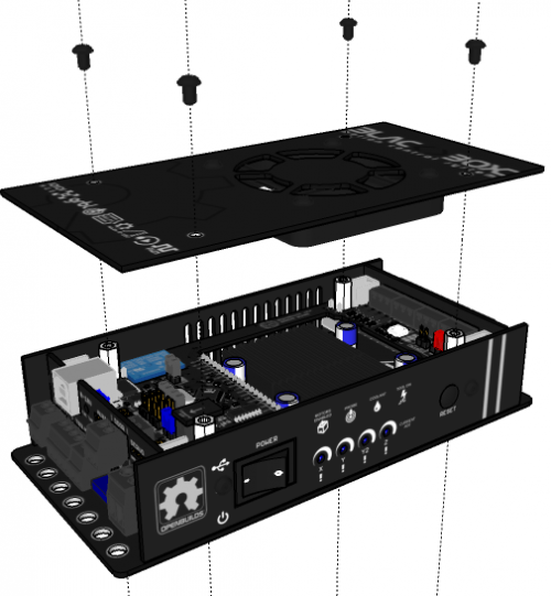
a) Remove the top panel of the BlackBox
Remove the 4 screws that hold down the top panel, and then set the panel with the fan attached to the side.
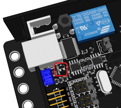
b) Remove Q25 / FDN340P Transistor near USB port
Right next to the USB socket, on the Brains board, is a transistor labelled FDN340P, or Q25, depending on the specific board revision. We will be removing this transistor from the Brains Board.
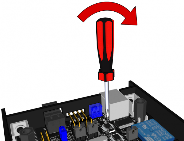
We have found a very easy, no desoldering required, method of just gently wedging the component off the PCB using a flat tipped screwdriver: (This will not void your warranty, as we approved the procedure)
- Position a flat tipped screwdriver so the tip is just between this transistor, and the USB socket
- Take care not to damage any other nearby components
- By levering against the USB socket, gently pop off the transistor from the PCB.
- Make sure to shake the transistor out of the BlackBox so it does not later fall into something it should not, and cause a short.
This modification allows Interface to communicate with the BlackBox V2.4, V2.5 and V.26 boards via AUX1. It does change one behavior of the BlackBox - it is no longer powered over USB - so the 24v power will need to be connected and turned on whenever you want to work with the BlackBox. As you need 24v connected and switched on for the stepper motors and other accessories as well, it will not be a noticeable difference to most users.
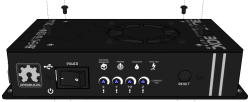
c) Replace the Top Panel
Make sure the Fan is plugged in - then place the top panel with fan back onto the BlackBox and reattach using the 4 screws you removed in step (a) above
Page Tools
All rights reserved. This Documentation or any portion thereof including but not limited to (menu structures, images, layout, videos, graphical artwork, logos, names, trademarks, etc.) may not be reproduced or used in any manner whatsoever without the express written permission of OpenBuilds, LLC


