Sidebar
Table of Contents
CNC Software Overview
A typical CNC workflow consists of three steps:
| CAD | CAM | CONTROL | ||
|---|---|---|---|---|
| Create Drawing | Convert to GCODE | Send to controller |
Within each of these, you have a lot of freedom to choose which applications you want to make use of in your own preferred workflow. You can select the ones you are most comfortable, or fit your sort of work better: For example, if your work is oriented toward signage and artwork, you'd prefer Vectric over Fusion360, because Fusion shines for engineering users who want to machine engineering type parts. If you run a Laser, you'd prefer Lightburn over the others as it focusses on Laser only.
1. CAD
CAD consists of applications you can use to create or modify 2D Drawings or 3D models, to use as input files for your CAM application:
TIP: Some CAM application also include CAD functionality, so you may see some applications listed and both sections.
Examples include:
- Fusion 360 ( Recommended) (2D and 3D)
- Sketchup MAKE 2017 Free (Recommended) (2D and 3D)
- Vectric Aspire/Cut2D/VCarve (Re commended) (2D and 3D)
- Inkscape (2D)
- Adobe Illustrator (2D)
- and many more
In most cases you export your drawings as CAM compatible files, for example
- DXF (2D)
- SVG (2D)
- STL (3D)
For more details, refer to Troubleshooting CAD files for help with file formats, and cleaning up files to make them ready for CAM.
2. CAM
CAM software converts CAD drawings/models to machine-readable GCODE that can be sent to your CNC Controller:
Examples include:
 OpenBuilds® CAM (Recommended) (2D CAM)
 Vectric Aspire/Cut2D/VCarve (Recommended) (2D and 3D)
 Fusion 360 (Recommended) (2D and 3D CAM)
 LightBurn (Laser specific CAM)
- SketchuCAM for Ske tchUp (2D CAM)
- svg2gcode Perfect for Pen Plotters
- Kiri:moto (3D CAM)
- FlatCAM (PCB Milling)
For more details, refer to CAM Applications for help configuring your CAM application with the correct Post Processor, etc
3. CONTROL
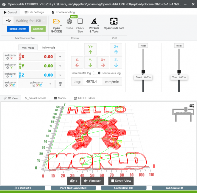
CONTROL software is tasked with streaming GCODE to your machine controller. It also handles all the other aspects of Machine interfacing, like Jogging, Digital read-outs, Alarm/Error handling, Serial Logging, Troubleshooting, etc
Examples include:
 OpenBuilds® CONTROL (Recommended) - Focused on keeping the learning curve to the minimum, helps you get started with the minimum of prior knowledge, yet still really powerful and feature packed with support for Probing, Macros, Machine Profiles, a 3D GCODE Viewer, Mobile Jog Widget, Surfacing Wizard and many more features. For more information refer to OpenBuilds CONTROL - Introduction
- Universal GCODE Sender Platform 2 - Suitable for slower computers
For example, OpenBuilds® CONTROL:
Page Tools
All rights reserved. This Documentation or any portion thereof including but not limited to (menu structures, images, layout, videos, graphical artwork, logos, names, trademarks, etc.) may not be reproduced or used in any manner whatsoever without the express written permission of OpenBuilds, LLC

