Table of Contents
Introduction to the OpenBuilds BlackBox Features
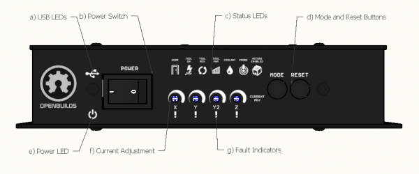
1. Front Side
- a) USB LEDs: Flashes in Blue/Green to indicate serial data transmit/receive traffic
- b) Power Switch: Used to turn the Main Power off, can be used in case of an emergency to bring the machine to an immediate stop
- c) Status LEDs
- Door LED: On when the Door input signal is active
- Tool On: Indicates the Tool is Enabled (Also Relay1)
- Tool Rev: Indicated Tool Direction is reversed (Also indicates Relay2)
- Tool PWM: Shows the proprotional RPM or output power of the PWM/0-10v outputs
- Coolant LED: Shows status of the Coolant signal (M8 = on, M9 = off)
- Probe LED: Lights up when the Probe Input activates
- Motors Enabled LED: Indicates when the firmware has the Motor Drivers Enabled. In Grbl Settings set $4=1 (required for BlackBox drivers to function correctly) and $1=255 (to keep motors always enabled)
- d) Mode and Reset Buttons: Reset: Restarts the Firmware; Mode button used to put microcontroller into Bootloader mode
- e) Power LED: If the Power LED is Green: Power Input OK
- f) Current Adjustment: Adjust stepper driver current, see Section 2.2.1 Current Adjustment
- g) Fault Indicators: Indicates a problem with the stepper driver on the relevant axis: The LED indicates
- Overtemperature Fault: Adjust current down a little, Check Fan
- Overcurrent Fault: Adjust current down a little
- Short Circuit Fault: Check Wiring
- Undervoltage: Check input Voltage
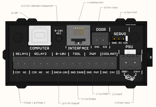
2. Left Side
- a) USB: Port for connecting the controller to your computer
- Drivers: Section 4.1 Install Device Drivers
- Troubleshooting: Section 6.3 Toubleshoot USB Connection / Firmware Not detected
- b) 0-10v Calibration: Used to calibrate the 0-10v Spindle control signal
- Calibration: Section 3.3.5 0-10v Analog Signal / VFD
- c) Interface Port: For connecting to accesories
- d) Door Switch Input: (Advanced feature) Refer to Section 3.6 Connect Door Sensor
- e) Servo: Used for pen-plotter applications: See Section 3.3.6 RC Servo
- f) Relays
- Relay 1: Normally Open SPST relay, by default configured as Tool Enable (Plasma trigger, VFD Enable, etc)
- Relay 2: Normally Open SPDT relay, by default configured as Tool Direction (VFD Direction, etc)
- g) 0-10v Output: Typically used with VFD Spindles. See Section 3.3.5 0-10v Analog Signal / VFD
- h) Tool Enable: 0/3.3V signal reflecting tool on/off state. Typically used as a logic signal for switching a Mains relay / IoT relay for spindle control
- i) Tool PWM: 0-3.3v PWM signal reflecting tool rpm/power. Typically used a PWM signal for DC motor controllers, Lasers, etc
- j) Coolant: General output, switchable with M8/M9, refer to Section 3.7 Coolant Output
- k) Power Input: Connect to 24v Power Supply. Double check polarity before powering on. See Section 3.1 Connect Power Supply
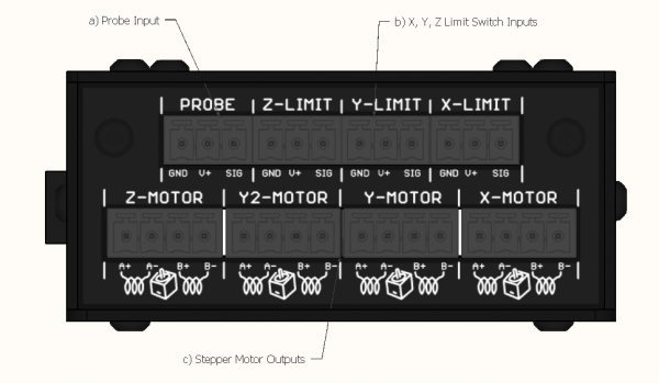
3. Right Side
- a) Probe Input: Connect to a Probe, see Section 3.5.1 OpenBuilds XYZ Probe Plus and 3.5.2 OpenBuilds Z Touch Plate as well as more information on XYZ Probe Plus Documentation
- b) Limit Switch Inputs: Connect Limit switches: See Section 3.4.1 OpenBuilds Xtension Limit Switches and 3.4.2 Micro Limit Switch Kit
- c) Stepper Motor Outputs: Connect motors: See Sections 3.2.1, 3.2.2 and 3.2.3) for connection details, and 6.1 Identify Motor Coils for troubleshooting information


