Table of Contents
11.1 Troubleshoot stepper motor wiring / Identify Stepper Motor Coil wiring pairs
11.1.1 Troubleshooting
If you have incorrectly identified the pairs, or made a wiring mistake where for example only 3 of the 4 wires are making good contact, then typically you will see one/more of the following symptoms:
- Motor running randomly in the wrong direction when you jog back and forth. Sometimes it follows the command, sometimes it does not.
- Motor vibrating in one place
- Motor moves, but very shakily, no smooth motion
- Lack of torque as the coils are not getting proper power
- Loud clanking or grinding noises coming from the motor, instead of the expected gentle humming sound
- Idling motors may produce more hissing or a high frequency noise, rather than a very gently hum
If this is the case, you can:
- Confirm that you have the coil-pairs correctly identified using the procedure below
- Using this procedure on the far end of any extension wires between the motor and controller, also allows you to validate the wiring itself, checking for broken connections between the side near the controller, and the motor.
- If you are 100% sure you have the coil-pairs correctly identified, typically the practical issue here would be only 3 of the 4 wires making good contact. Go over each joint and check that no insulation are being squashed into a terminal, and that all wiring are solidly inserted into all terminals. You can also check the wire with a multimeter in continuity mode to ensure the wire did not break off inside.
11.1.2 Identifying Stepper Motor Coil wires
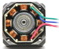
A stepper motor is a type of brushless motor, consisting of a permanent magnet Rotor, and two static 'stator coils' inside the housing (for the purpose of our typical configurations, these are called Bipolar Stepper motors, there are other less popular configurations such as Unipolar as well, but usually these not applicable to our typical configurations. This section deals with Bipolar 4-wire motors specifically)
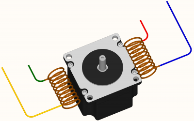
These two coils are wrapped into a complicated stator pattern inside the motor, but electrically, it is just two coils of wire each with a wire on each end of the coil.
Imagine for a moment, that you could see these coils inside the motor: It would looks something like this (simplified) - where there are two coils, each with a wire on each end. This typically gives you 4 wires coming out of the motor.
A special “stepper driver” controls the motor by switching power to these two coils in a controlled manner. For that to work, the correct motor wires need to be attached to the correct outputs on the stepper drivers. This section will help you identify the correct wires that form a “pair” belonging to the same coil, for motors where you are unsure of the wiring order, cannot find or trust the color code, or those where you do have not got access to datasheets or other reliable information. You can also use this to test your motors, motor wiring, and confirm that you have the correct wires “paired” together.
Since you cannot actually see these coils as the simplified visualization shows them, you need to identify which wires belong to each coil, electrically.
There are two different techniques, easiest is if you have access to a Multimeter (Section 3), but you can also do it without a multimeter (Section 4). Note the Multimeter based procedure is more reliable.
11.1.3 Procedure (with a Multimeter)
11.1.3.1 Set your Multimeter to Continuity
Set your Multimeter to Continuity / Diode Test mode:
11.1.3.2 Connect the Negative probe
Start with any random wire, and touch that to the Black/negative probe on your multimeter
11.1.3.3 Test first wire
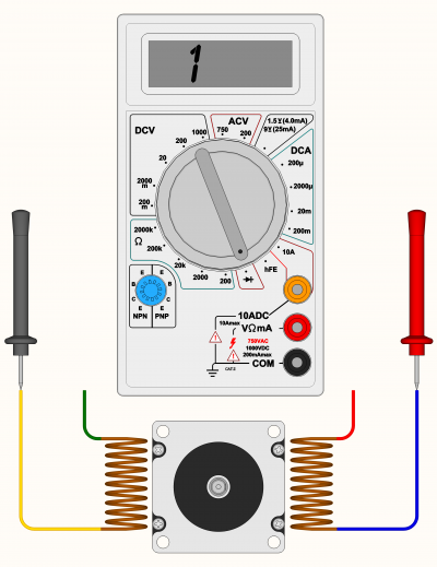
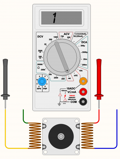
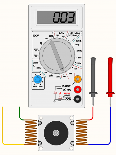
Select any remaining wire and touch it with the Red/Positive probe of your multimeter: You have a 33% chance of finding that first wire's companion on the first try, but lets assume you did not. Thanks to our visualisation of the coils, you can see that we hit a wire belonging to the other coil on our first try. So that's not the one we are looking for… If the Multimeter shows [1] it means “no connection” - indicating we did not find a coil between these two wires. Some multimeters also “beep” when it does find a connection, so if there is no beep noise, it also could indicate the coil is not between these two wires
11.1.3.4 Test another wire
Let's try another wire, again a 33% chance you are going to find the one we are looking for. Keep the Black/Negative probe on the wire from (2) above. As you can see, multimeter is still showing us [1] (and no 'beep') so we still did not find the wire that pairs up with the wire touching the Black probe…
11.1.3.5 Test correct wire
Moving to the last remaining wire, we finally see a reading on the multimeter. The actual number does not matter too much, its more important that it has some low value reading, and that the multimeter no longer displays [1] on the display. Some multimeters may “beep” when you have continuity between the wires (circuit completed by the coil in between)
Segment off these two wires and label them as belonging to a coil.
You can wire these two wires, to A+ and A- on your stepper driver
11.1.3.6 Confirm remaining wires has a coil
Lets just probe the two remaining wires to make sure there is a coil between them: If there is, as shown below, label these two wires as belonging to a coil. Display should show a reading, and the multimeter may beep
You can wire these two wires, to B+ and B- on your stepper driver
11.1.4 Procedure (without a Multimeter)
11.1.4.1 Twist together two random wires
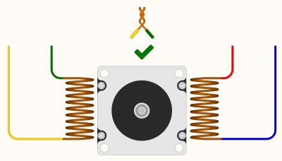
Start by taking any two random motor wires and twisting/touching them together as shown. If the two wires you joined together, belong to one coil, they will self-induce a magnetic field in the motor when you try to turn the shaft by hand. This will be noticable with an increased resistance against turning, and may even feel like you are turning against a clicking feeling. If that shaft still spins easily, you have not identified a coil yet
11.1.4.2 Try a different combination
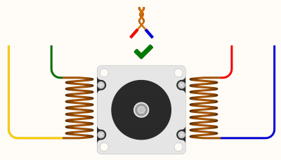
If you have not identified a coil yet, disconnect the two wires joined together before, and join a different pair. In the example below, you can see that this wire pair still does not belong to the same coil. If the two wires you joined together, belong to one coil, they will self-induce a magnetic field in the motor when you try to turn the shaft by hand. This will be noticable with an increased resistance against turning, and may even feel like you are turning against a clicking feeling. If that shaft still spins easily, you have not identified a coil yet
11.1.4.3 Find a valid combination
If you join together two wires that do result in the motor presenting resistance against turning, you can label these two wires as belonging to the same coil, and wire them to the A+/A- outputs of your stepper driver
