Table of Contents
1.1 Assembly Instructions
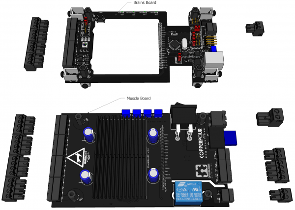
1. Unplug the screw terminals from Brains and Muscle
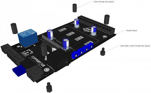
2. Add Hex Spacers to the Muscle Board
Take the MUSCLE BOARD, and install 4x M3 6mm Male x 6mm Female Nylon Spacers and 4x M3 12mm Female Nylon Spacers as shown
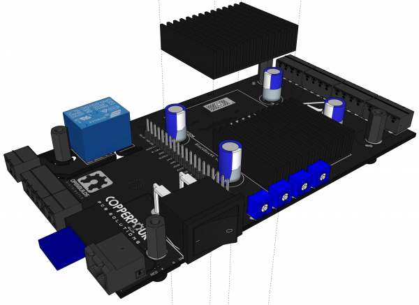
3. Install the Heatsinks
Remove the protective backing from the self-adhesive thermal pads on the rear of the 2x 32x40x11mm Heatsinks Carefully stick the heatsinks to the MUSCLE board as shown.
NB: Make sure to line the heatsinks up within the printed boundaries on the PCB and ensure proper adhesion for optimum thermal performance
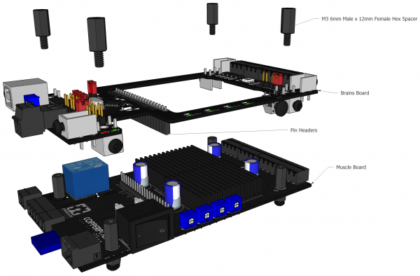
4. Add the Brains board onto the stack
Add the Brains board onto the stack. Tighten it down using 4 x M3 12mm Female x 6mm Male Nylon Spacers as shown.
NB: be very careful to align the two boards together and ensure the interconnect Pin Headers make a solid connection. Also make sure the connector is not offset / bent / incorrectly plugged in.
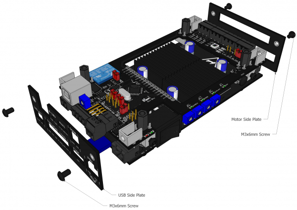
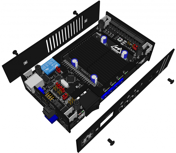
5. Install the Side Panels
6. Install the Button Cap on the Reset Button
7. Install the Front/Back Panels
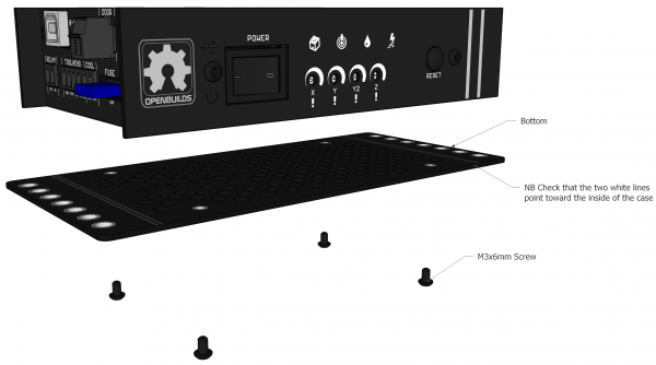
8. Install the Bottom Panel
Install the Bottom Panel using 4 x M3 x 6mm Screws as shown
NB: If you check the bottom plate, one side has two lines running over it. Attach the bottom plate so these two lines point inward, lining up with the plates you installed in step 5
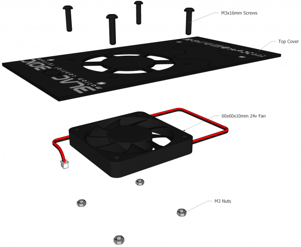
9. Assemble the top cover / fan sub-assembly
Attach the 60x60x10mm 24v Fan using 4 x M3 x 16mm Screws and 4 x M3 Nuts
NB: Check the airflow direction of the Fan itself: Ensure it will be blowing downward onto the heatsinks, pulling cool air into the case from the top. IE: Mount it so that the side of the fan with the sticker, faces toward the heatsinks.
10. Plug in the Fan
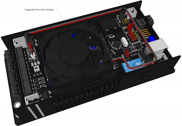
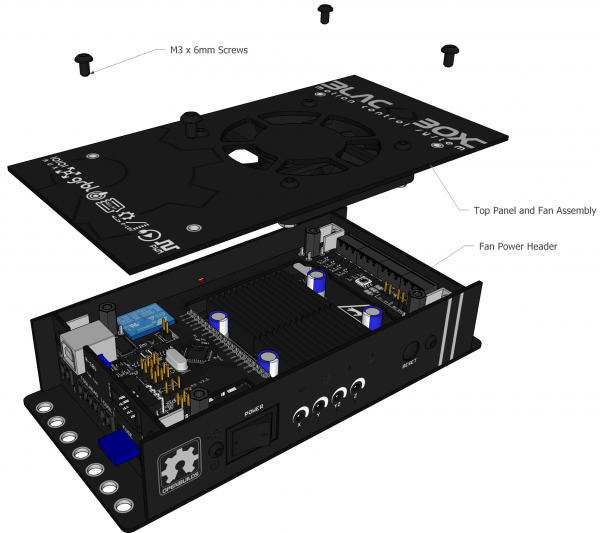
Plug the fan's Power Lead into the Fan Power header on the Brains Board. The image below is shows the suggested wire routing (Pictured as if the top cover is invisible)
NB: Check your fan wiring polarity. Make sure to line up the RED wire on the plug with the + symbol on the board, and the BLACK wire with the - symbol.
11. Attach the top cover / fan sub-assembly
Attach the top cover / fan sub-assembly from the prior step to the BlackBox using 4 x M3 x 6mm Screws
TIP: Before closing the TOP Panel, you might want to check section 2.1 of the documentation, if you need to change any jumpers it's easier to do before closing the top.
